Raditeq | FAQ
FAQ Categories
Find you Answer!
Welcome to the Raditeq FAQ page! Whether you’re a new customer or a seasoned user, this section is designed to help you find answers to common questions about our products, services, and technologies. Troubleshooting has never been easier as we’ve compiled the most frequently asked questions to ensure you have all the support you need. If you don’t find the answer you’re looking for here, our dedicated support team is always ready to assist. Explore below and get the insights you need to make the most out of Raditeq’s cutting-edge solutions!
Search your question
RadiSense | Electric Field Probe
The RadiSense probe is always measuring in rectangular coordinates, since all three axis’ are orthogonally aligned. In theory it does not matter how the sensor is placed in the field, it should always indicate the same total E-field.
The total field is calculated by Etot = SQRT (Ex² + Ey² + Ez²).
Nevertheless, no E-field sensor is perfect due to probe shape, probe dimensions, field perturbation and anisotropy small errors will exist. Therefore, it is recommended to place one of the axis’ parallel to the field. This can be accomplished by placing the sensor in such a way that one element has the same direction as the elements of your radiating antenna.
 0
0
 0
0
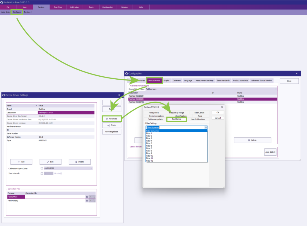
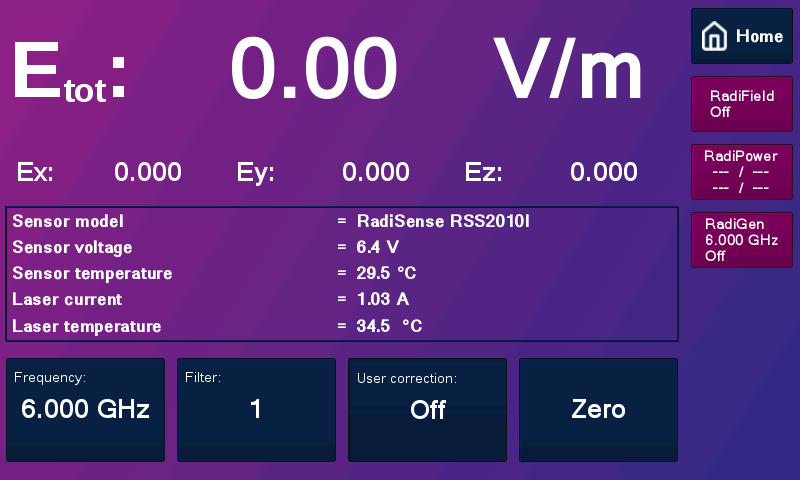
When starting up the the RadiSense® and measuring at low E-field levels or frequency the reading can be unstable. This is due to the internal filtering in the field probe. The filtering is set as a standard to the “Dynamic” setting. This means that it is searching for the most stable reading. In cases of low test levels and/or frequency it is impossible to find this stable reading for the probe and the filter setting needs to be changed from Dynamic to Filter 6 or higher. This will make the reading stable for read-out.
This can be done through RadiMation under the advanced settings of the probe

The filter setting can also be changed using the RadiCentre® CTR1004 and CTR1009 using the touch screen.

 0
0
 0
0
No, this is not needed anymore! The RadiSense® 10 probe has the capability to store the x, y and z-axis frequency response correction data from an ISO17025 accredited calibration certificate internally inside the field probe as ‘user correction’. In this way you cannot make any mistakes like applying the wrong axis factors and/or forgetting to apply the corrections. As a result of this feature, you can achieve higher quality EMC testing.
 0
0
 0
0
In case the calibration is being performed at KIWA dare Calibrations (ISO107205 accredited of E-field probe calibrations) this is not needed. The calibration labs at DARE!! Calibrations are equipped with multiple RadiCentre + LPS2001B systems that can be used to operate the RadiSense 10 field probe during calibration. In this way the transportation costs and damage risks are minimized. The calibration results (frequency response X-Y-Z, linearity and isotropy) are provided as an ISO17025 calibration certificate (Adobe® PDF format) as well as in electronic format (MS® Excel file).
 0
0
 0
0
General Questions
Request general information
If you have general questions about all products or our service surrounding them please leave a question here or mail us!

