The Standard
Performing Field uniformity and TEM mode measurement | According to 61000-4-20 in chapter 5.2 a “Field uniformity and TEM mode measurement procedure” has to be performed. In this procedure, next to the Uniform Field Area (UFA) procedure, it is described that the difference between the primary and secondary component should be verified. Therefore in the following steps it is described how to perform this verification with RadiMation.
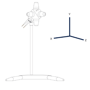
Field uniformity and TEM mode – Test setup
Position the field probe with the Y axis positioned in the field (straight up) on one of the required points of the UFA. Check out the most accurate Field probe here: RadiSense® Series
Configuring RadiMation for Field uniformity and TEM mode measurement
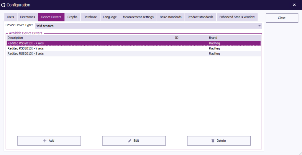
Add and configure field probe drivers
It is important to have three (3) device drivers in RadiMation for the same physical field probe, to allow that the field components of the individual X, Y and Z-axis can be measured. After this add and configure three (3) Field Sensor device drivers in RadiMation which are measuring the three (3) different axis.
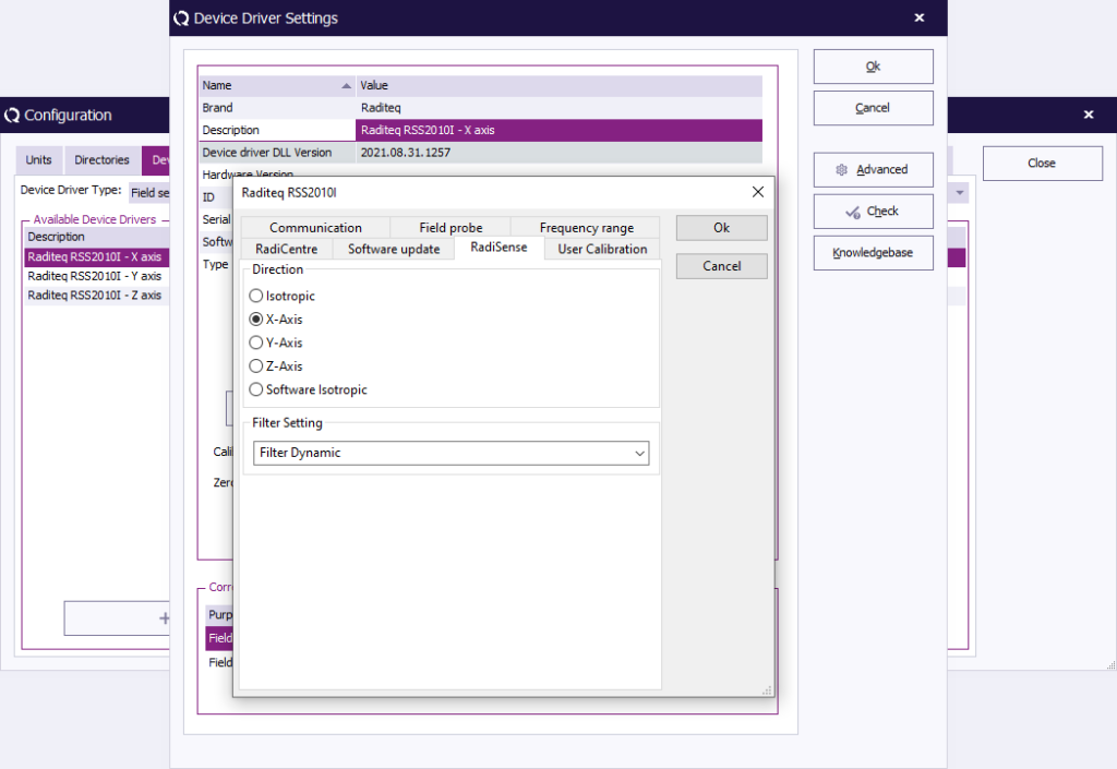
Open the driver configuration of each driver and click “Advanced” and choose the tab RadiSense and select the applicable axis, X, Y or Z
Create a test site in RadiMation
Select the applicable hardware that will be used for immunity tests. This normally consists of the following device types:
- Signal Generator
- Amplifier
- Coupler
- Antenna
- Forward Power Meter
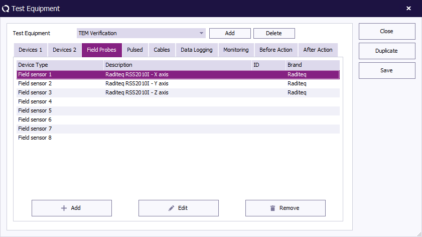
Add/define the axis of the probe as followed:
- the X-axis field probe as Probe 1;
- the Y-axis field probe as Probe 2;
- the Z-axis field probe as Probe 3.
1 Point Calibration
To calibrate one point execute the following steps:
- Start by Closing any open EUT files if needed and start a “1 Point Calibration”;
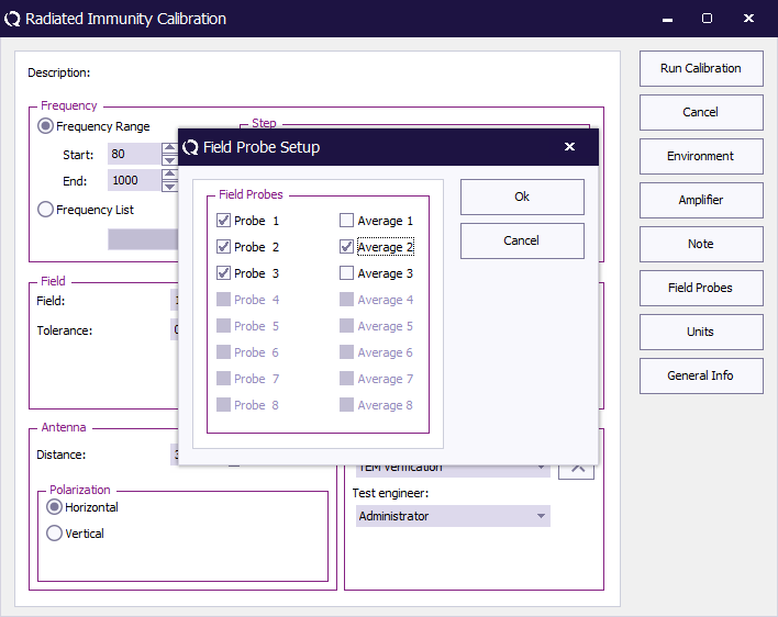
- Configure the Frequency Range, Step, Level, Method and Distance;
- Click “Field Probes” and select Field Probe 1, 2 and 3. But only apply averaging for the field probe 2; This corresponds to the Y-axis on which the calibration should actually be performed;
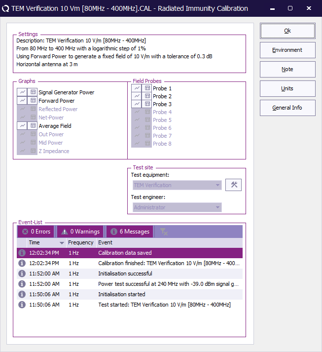
- Run “Calibration” and save the TSF configuration for later use;
- When the calibration is finished, save the Cal file, for example as “Point <n>.cal”;
- Run the calibration for all other points and use the saved TSF configuration.
Open calibration data
When all points are measured the Calibration files stores all the data accessible from Excel.
Thereafter in Excel it can be determined if the secondary component does not exceed -6 dB of the primary component.
lastly after opening the cal file, click the icon in front of the “Probe 1” to open the result.
Then select the other probes as shown:
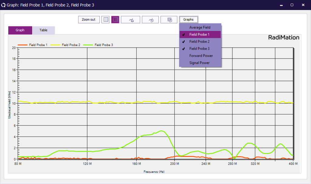
To copy the data to excel, click the button next to the “Graphs” button to afterwards paste it in an empty Excel sheet.
Uniform Field Area Calculation – UFA
To calculate the UFA start an “Uniform Field Area Calculation”.
- Firstly Add all calibration files belonging to the UFA.
- Secondly Select “EN 61000-4-3 2010 Constant field method” as calculation method.
- Thirdly Choose “Calculate”.
- Finally Save the resulting Cal file which can be used in an immunity test for a substitution test level.